
System Simulation
Modern design of electrical energy conversion systems -which includes power electronics- require the support of simulation tools. A system or circuit simulation alone is no longer satisfactory without proper combined-physics system analysis and design. Understanding the strengths of different tools and integrating them in the design process allows investigation of more design aspects than only circuit simulation. Typical simulation analysis of combined physics consists of many aspects that are modeled into the combined circuit-system simulator. These are, for example, parameters of magnetic actuators, parameters and precise models of semiconductor switches, electrical machine parameters, thermal effects, different control issues, or packaging and parasitic effects as a result of different layout. All electromechanical systems require a power source. Ultimately, the entire system, including all mechanical, hydraulic, and thermal loading needs to be modeled. The interaction and data exchange with different analysis and design tools are hereby necessary.
Electrical Machines and Drives
| Electrical machines are the modern workhorses of the industry. Fast conceptual designs, and easy-to-use models that can be parameterized based on the nameplate, save modeling time. Detailed modeling, where imported models from FEM are used, is key to optimize drive train design.
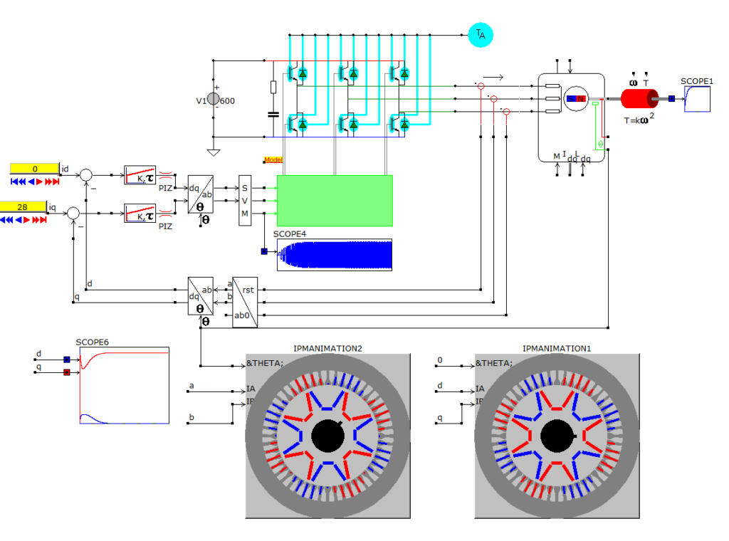
Modern electrical machine concepts like field weakening in interior permanent magnet motors or direct torque control in switched reluctance machines, require an extensive set of specialized models. The electrical machine and drives library in CASPOC includes all basic building blocks for a successful implementation of the entire drive system. The variety of machine models in the library covers most commonly known electrical drive concepts. Specialized machine models are easily set up using these basic building blocks. |
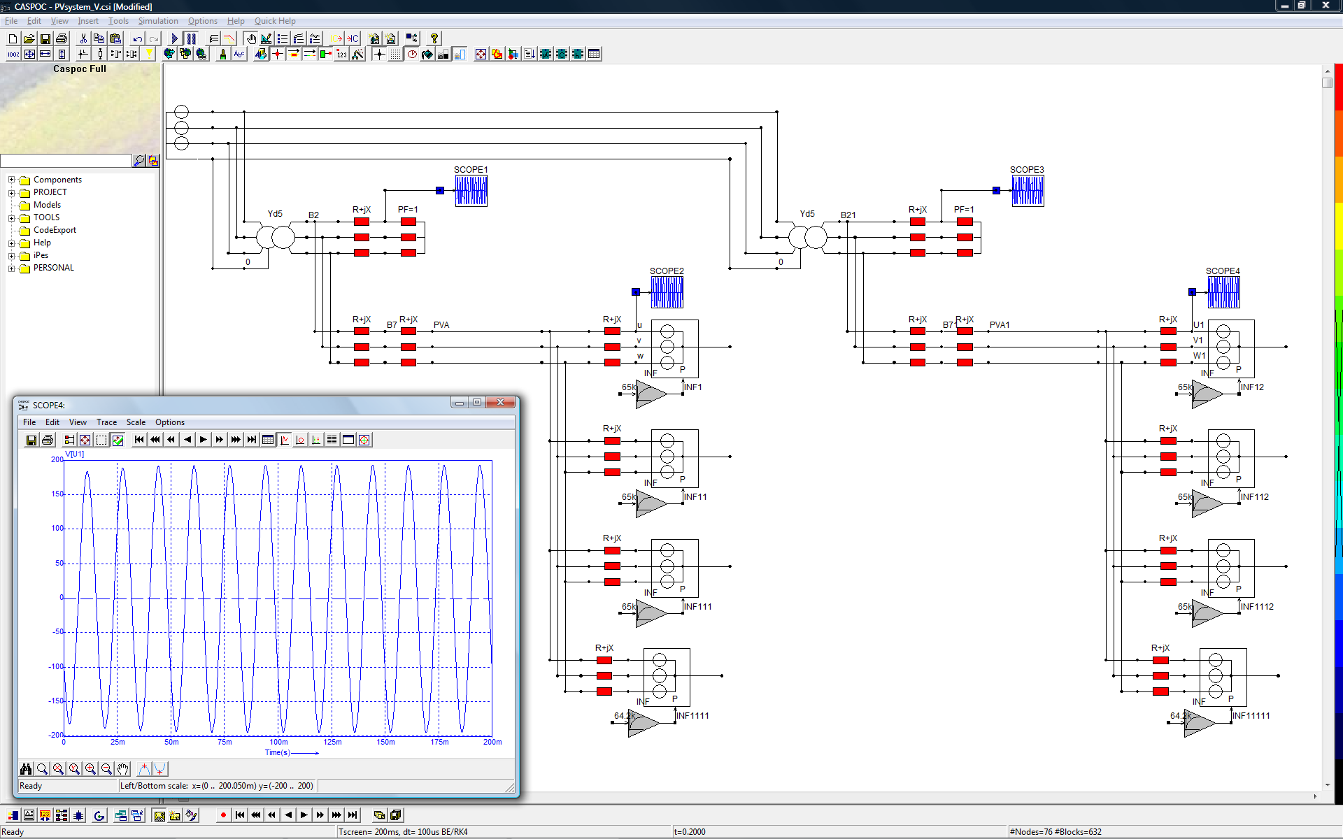
Grid Connection
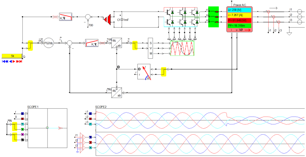
| The grid-connectors are critical devices which transfer the accumulated green energy from wind and solar power systems into the main grid. The single-phase grid connection for PV and wind power systems is one of the key components of stable and efficient power transfer into the grid. Grid-synchronization, EMI problems, harmonic regulations and efficiency are design issues involved in the definition of a model.
Detailed modeling of the grid synchronization and modulation techniques, as well as power electronics technology, are required in the modeling of grid converters for green energy. Quadrature controllers, analogous to field oriented control in electrical drives, allow the control of active and reactive power in both single and three phase grid connections. CASPOC empowers engineers to simulate important factors such as modulation strategies, loss determination and thermal cycling, as well as life time estimation. |
High Efficiency Variable Speed Drives
| Optimizing the efficiency in variable speed drives can offer some impressive energy savings: the energy saving potential can go up to 10% for high efficiency motors, 30% by using frequency converters and an astonishing 60% by optimizing the entire drive train, according to the German Electrical and Electronic Manufacturers’ Association, ZVEI (Source: “Energiesparen mit elektrischen Antrieben”, ZVEI Broschüre, April 2006).
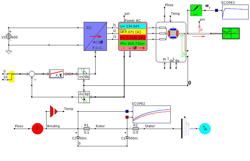
By using FEM , the losses in high efficiency motors (like induction machines and permanent magnet synchronous machines) can be minimized. CASPOC imports the model including the information on the efficiency of the motor. The program simulates the efficiency of the entire variable speed drive depending on various operation conditions. CASPOC allows the simulation of the entire drive train including the inverter, control and mechanical load, so efficiency and controllability can be optimized. For various load conditions, losses in the power electronics and the electrical machine can now be minimized, so your products comply with the new international efficiency classes IE2 and IE3. |
High Precision Servo Drives
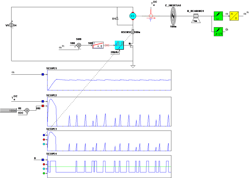
| The accuracy of servo drives depends on all components in the drive train. Every non-linearity or drift in encoders, quantization of current and voltage measurements, delay in control algorithms and even the back-lash in gear boxes have to be included in the simulation model. The multiphysics library in CASPOC includes special models from which the entire servo drive can be built.
Highly detailed electric machine and single phase actuator models (including all position and saturation as well as efficiency data) are calculated in FEM and imported into CASPOC for a complete drive simulation. By using the generic electrical machine and generic control blocks, a drive train concept is easily set up. From a concept to a ready-for-production prototype, detailed electrical machines can be modeled from FEM, including all delay and non-linearity in each and every component. |
Hybrid and Plug-in Electric Vehicles
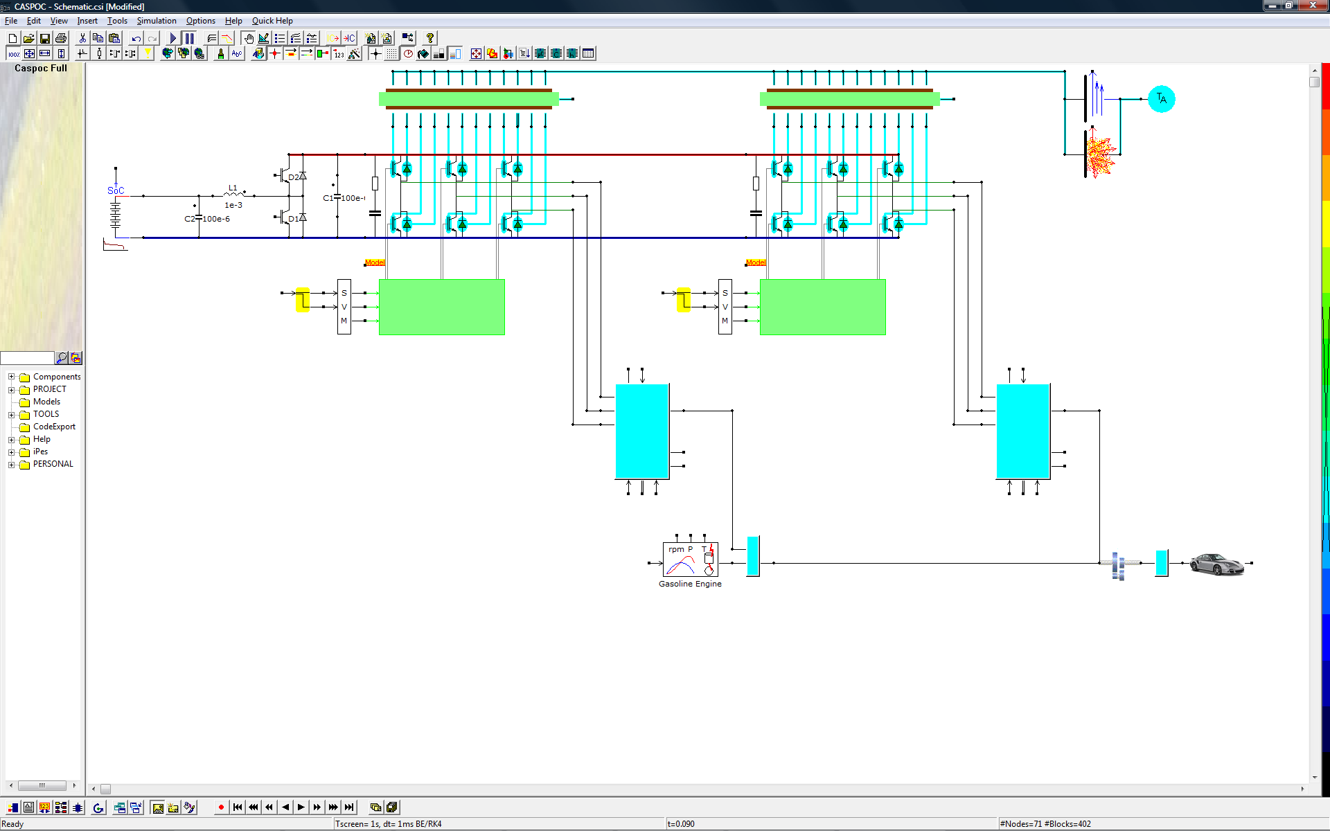
| As fossil resources diminish day after day, electric mobility clearly emerges as the most desirable technology. The future of transportation will be shaped by electric vehicles. At the moment, the main advantage of liquid fuel is the high energy density when compared to other portable energy storage mediums.
Electric and hybrid vehicles are considered to be the most important research topics in the field of worldwide energy mobile consumption. In order to be mobile, energy produced by wind and solar technologies has to be stored for later mobile use. CASPOC offers design engineers the best suite to analyze their systems:
|
LED lighting
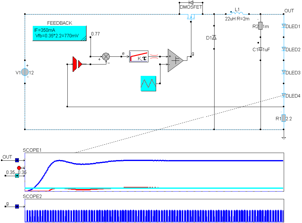
| LED lighting is revolutionizing our cars and homes. Nowadays, every modern passenger car is equipped with LEDs. Headlight, brake and rearlight are sophisticated LED designs that include numerous LEDs and driving electronics. The design of power electronics for the LED driver and the thermal layout of the LED armatures are key to successful LED design. Detailed switched-mode-power-supply design in CASPOC includes modeling the power converter stage with all parasitic components, as well as the control, either by micro-controller or specific analog control IC.
|
Power Electronics Losses Thermal
| When modeling wind power and solar systems, detailed power electronics converters are key: the control of the generator takes place via power electronics, and the calculation of losses of the power electronics has to be modeled in detail. The modulation principle has a strong impact on the generation of harmonics on the grid side.
In hybrid and electrical vehicle simulations, a virtual driver allows testing a model against a given time-speed characteristic. Once the inverter components are modeled in detail (including the loss calculation), the thermal behavior of the power electronics can be studied in detail. The virtual driver controls the field-oriented controller which, by using space vector modulation, oversees the power electronics inverter. The semiconductor models in CASPOC are directly coupled to a thermal model, meaning that during the simulation the parameter dependency on junction and heat-sink temperature are taken into account. During the simulation, the thermal cycling is calculated, allowing the estimation of life time. CASPOC includes special blocks for modeling space vector modulation. This is required since the harmonics generated by this type of modulation influence both the losses in the power electronics and electrical machine, as well as the dynamic behavior of the electrical machine. |
Power Electronics
| Power electronics is the key component in current sustainable energy technology. It is the interface between the source of energy and the consumer. Specialized models in CASPOC allow design engineers to model all phases in modern power electronic designs, not only electrical, but also in magnetic and thermal design.
Whether you are designing on the micro-power level or for high power utilities, power electronics principles can be modeled in CASPOC. Converter structures ranging from basic switched model power supplies, controlled rectifiers, inverters with synchronous rectification up to multilevel inverters are modeled in CASPOC for a conceptual or detailed design. |
Power Systems
| Today, the generation and distribution of electrical power is becoming more sophisticated because of the scattered locations of the new renewable energy sources and consumer demands, like charging electrical vehicles. Micro-grids or smart grids, stability, and harmonics remain issues in these highly connected highways for energy.
Accurate generator modeling and power electronics modeling for VAR compensation and FACTS remain key issues. The extensive power systems library in CASPOC allows the modeling of harmonics and stability in small scale grids, like micro grids and islanding mode. |
Solar Power
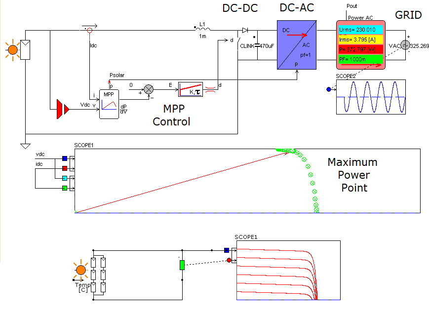
| Currently, solar energy generation is a highly valued renewable energy generation method. Use of engineering simulation software like helps with the optimization of entire designs, whether it is a small-scale solar project or a large remote solar harvesting park.
The complete system (solar power + grid connection) can be modeled, from varying sunlight density to grid connection. Engineers can either work with a standard model or enter the specific features provided by the manufacturer. CASPOC is the best solution for solar power systems analysis.
|
Wind Power
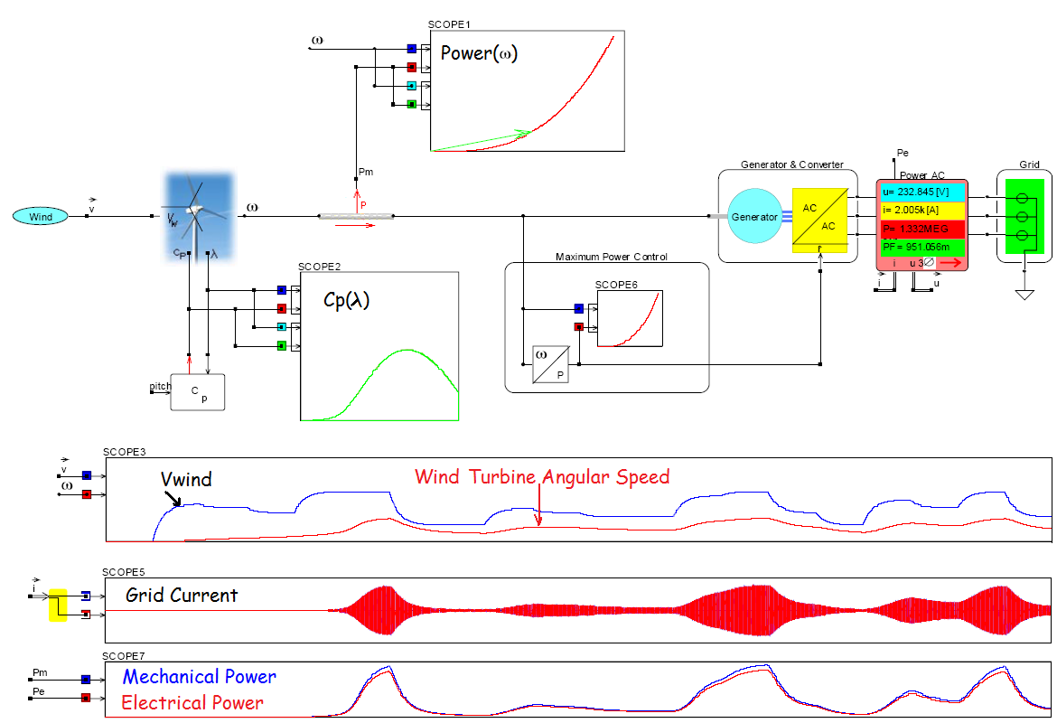
| Model a complete system, from varying wind speed to grid connection.
The design optimization of generators powered by wind energy requires knowledge of electromagnetic energy conversion; in wind power systems, the control is clearly dependent on the wind speed. CASPOC analyzes the efficiency of a wind power generator in order to:
Some features in CASPOC:
|
Examples in the viewer and Workbooks
A number of pre-built examples are provided together with Caspoc. Below are descriptions of selected examples in Caspoc (there are more examples than listed below), located in the examples sub-folder of the Caspoc installation directory.
Small signal AC Analysis:
- Open-loop transfer function of a buck converter in switchmode
- Closed-loop transfer function of a buck converter in average model and in switchmode
- Impedance of an RC and LC filter
SMPS Controller Design
- Buck converter with inner current loop and outer voltage loop, with the buck converter implemented in Caspoc with current and voltage regulators.
- Control loops of a PFC (power factor correction) boost converter, with converter implemented in Caspoc and the current/voltage regulators.
- Peak Current Control of a DC/DC converter
- Digital control loop of a buck converter
Co-Simulation with Matlab:
- Buck converter with current feedback, with the power circuit implemented in Caspoc and the control parameters calculated in Matlab. The Caspoc model is started from Matlab.
- Wireless power transfer system with the power circuit implemented in Caspoc and the parameters calculated in Matlab. The Caspoc model is started from Matlab.
Inverters:
- Implementation of space vector PWM for 3-phase voltage source inverter (VSI)
- Multi-level inverter
- 3-phase VSI with Sinusoidal PWM, in switching function implementation, and average model implementation.
- 3-phase VSI with selective harmonic elimination(sample in the drives workbook)
- On-line gating signal generation of 3-phase PWM current source inverter
- Inverter dead time circuit
DC Switchmode Power Supplies:
- Full-bridge dc/dc power supply with coupled inductors
- Flyback converter with coupled inductors
- Push-pull converter with current control
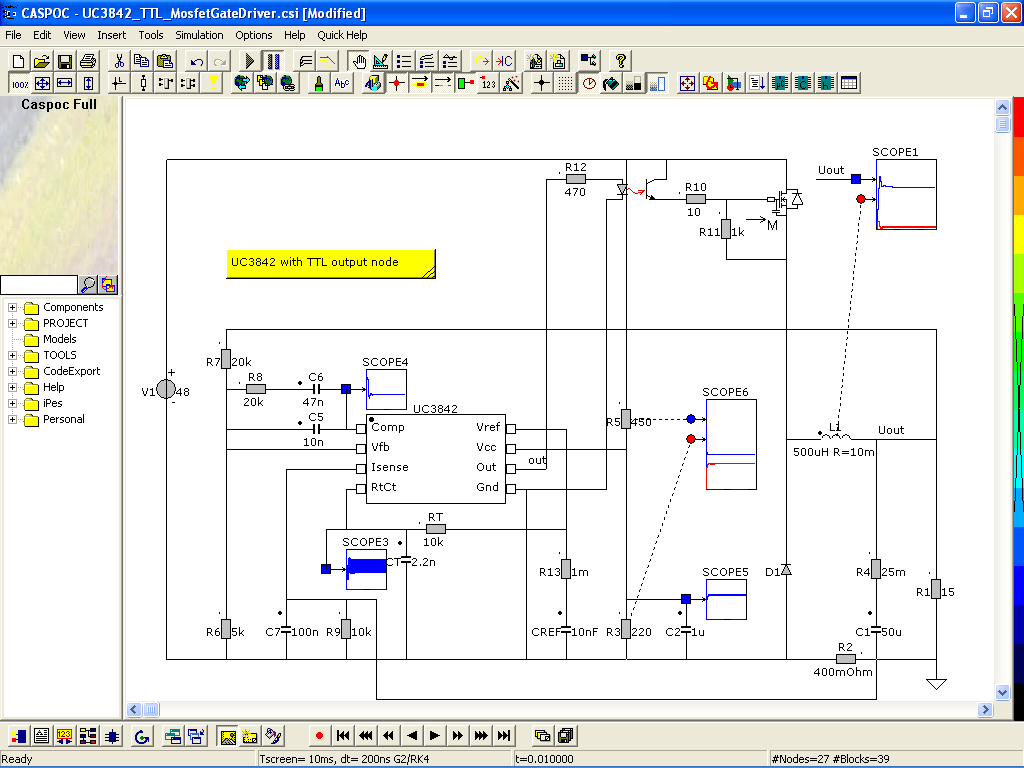
PWM IC Models:
- Unitrode current mode PWM controller IC UC3842/3843 with a buck converter example
- Voltage mode PWM controller IC MC34063 with a buck converter example
- Unitrode current mode PWM controller IC UC3844/3845 with a flyback power supply example
- Unitrode PWM controller IC UC3854 with a power factor correction example
- Unitrode high-speed PWM controller IC UC3823A|B/3825A|B with a push-pull converter example
Rectifiers and Cycloconverters:
- 3-phase PWM rectifier
- 6-pulse rectifier and 12-pulse rectifiers(sample in the PE workbook)
- 2 phase-controlled bridges in parallel with interphase transformer(sample in the PE workbook)
- Cycloconverter circuit
PFC; Active Filters; Control Loops; and Other:
- Boost power factor correction (PFC) circuit
- PFC circuit with inner-current-outer-voltage loops implemented
- 3-phase ac active filter(sample in the PE workbook)
- Phase-lock loop
- Voltage-controlled oscillator (VCO)
- Hysteresis (bang-bang) comparator
- Schmitt trigger circuit
- Free-running square-wave oscillator circuit
Zero-Voltage-Switching (ZVS) and Zero-Current-Switching (ZCS) Circuits:
- ZVS flyback converter (sample in the PE workbook)
- ZCS flyback converter (sample in the PE workbook)
- ZVS resonant switch (sample in the PE workbook)
- ZCS resonant switch (sample in the PE workbook)
Linking External C/C++ Code via DLL:
- Calculation of rms values using built-in RMS block and external C routine
- Calculation of First Order Filter using built-in INF block and external C routine
- Solving of Non-Linear function using external C routine
- Boost power factor correction circuit with digital inner/outer loop controllers implemented in a C routine
Digital Control; Discrete Systems:
- Boost power factor correction circuit with digital inner/outer loop controllers
- Digital implementation of space vector PWM for 3-phase voltage source inverter (VSI)
- 2nd-order analog and digital filters
- Different ways of implementing a digital integrator
- Digital implementation of rms calculation
Motor Drives:
- Induction motor drive system(sample in the Drives workbook)
- Start-up of an induction machine
- DC generator-motor set(sample in the Drives workbook)
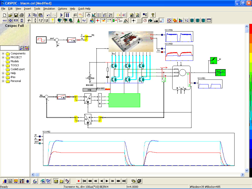
- Start-up transient of a brushless dc motor
- Speed characteristics of a brushless dc motor under dc bus voltage change
- Speed control of a brushless dc motor drive system
- Induction motor drive with long cable and high-freq motor model
- 3-ph PMSM drive with current control
- 3-ph IPM drive with current control and animation